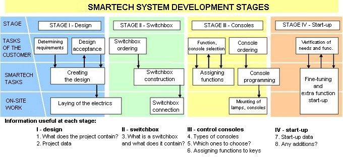
SMARTech system development stages

Stage 1 – the project
The project of a SMARTech system consists of:
- floor plans with all electrics and cabling marked (lighting, outlets, blinds, consoles, etc.),
- a description for the electricians laying the cabling,
- a description of the implemented system to control the lighting, heating/air conditioning, floor/staircase/gully/driveway heating,
- a description of the gate control scheme,
- a description of the integration scheme with the alarm system, phone and audio/video network,
- plans for the installations and schematics of the switchboxes,
- calculations of cable lengths and sizes.
Stage II – The switchbox – what is it and what does it contain?
The switchbox is the heart of the electrics, all cabling (from in- as well as outside the house) is routed to it. Here the power is divided among different outlets, lamps and appliances. SMARTech-built switchboxes contain:
- a main switch allowing one to cut all power to the house instantly
- for larger buildings, an emergency fire switch (a switch located at the entrance to the building), cutting power to all appliances except selected ones (emergency lighting, pumps), e. g. in case of fire so that the fire brigade could begin putting the fire out (they would not start unless the power was cut),
- phase control meter, telling us whether one of the phases was cut or not,
- surge protectors – currently, buildings use a lot of devices that are sensitive to minute power surges that could lead to equipment damage. A surge protector is used in just such cases.
- residual current protection – protects from intermediate touching. Should a live wire be touched by someone, it will be automatically and very quickly shut off. Theoretically such a touch will not be felt. Additionally, such protection makes sure that no dangerous current appears on the casing of an appliance (e. g. the washing machine) and protects from fire.
- overcurrent protection – the system shuts off the circuit should there be a short circuit or should power uptake become too high (e. g. if there are too many appliances connected to one socket), which protects from overload and fire.
- automation modules (binary gates to connect lamps, outlets, gates, ventilation, dimmers, blind control, power supplies, communication connectors, etc.
- grippers to connect sometimes hundreds of wires in this 'little box’.
An example of a switchbox for a 200 sq m house is shown below:
Stage III – control consoles
Our customers are free to choose the devices visible in the rooms (consoles, motion detectors, LCDs, etc.), depending on their abilities and needs as to functionality and aesthetics. We offer devices by many various manufacturers (e. g. ABB, Berker, Gira, Hager, Jung, Merten), which provides a wide selection without any single manufacturer being favoured. You will find the details in a separate document.
Foremost, however, one has to determine what functions they should fulfil. These are as follows (in brackets the number of keys a function needs):
- switching a lamp or an outlet (1)
- switching + dimming a lamp (2)
- roller blind or marquee control, or a group thereof (2)
- opening/closing of a gate, entryway, roof window (1)
- control of a scene or a central function (1)
- an off function – to turn off all the lamps, e. g. when everyone leaves or before a scene is lit (1)
Examples of scenes and central functions:
- scenes: guests, cleaning, afternoon coffee, movie, reading, banquet, cooking, dinner, date, sleeping (all lamps off, all blinds shut, alarm armed), wake-up, alarm (external lamps on to scare the intruder away)
- exit from the room (all lamps off)
- exit from the house (all lamps off, all blinds shut, reduced heating)
- return to the house (a few lamps switched on, selected blinds are opened, heating back on)
- opening/shutting of all blinds
- all external lamps on (possible also automatically at dusk)
What can be controlled? The lighting, air conditioning, heating, air humidity, roller blinds, marquees, curtains, blinds, gates, roof windows, heating of gullies and the driveway (to prevent frost), arming of the alarm (disarming only manually from keyboard).
Stage IV – system start-up
In order to be able to create a system according to your needs we must get to know them first, meaning it is imperative that you write them down. Please consider, what would you like to be controlled by radio remote controls (e. g. entrance gate, garage door, lighting in the garden), whether the system should react to outside conditions, and how (e. g. turn on the lights in the garden after dark and lower the blinds, reduce the heating after everyone leaves, etc.).
In order for the SMARTech system to be integrated with other systems one has to specify which triggers or signals should be used by the system – e. g. an intruder alert (to turn on the lights and show the person), an open window signal (to switch off the heating in that room), water overflow in the bathroom (to cut the water to the washing machine), etc. You should also specify whether there should be any signals from the SMARTech system that are directed to any external devices, e. g. a signal to switch off the heating/air conditioning, a signal to the GSM communicator module, etc.
Should you want to be able to view the system status via the computer, a display, etc., you should specify, which signals from the system (also the ones from external systems) should be included (e. g. temperature measurements for every room with adjustment option, information on open windows and functioning special appliances such as pumps, etc.).
